NCERT Solutions Class 12 Physics Electromagnetic Induction
NCERT Solutions Class 12 Physics Electromagnetic Induction Chapter 6 is a part of NCERT Solutions Class 12 Physics. Here we have given NCERT Solutions Class 12 Physics Electromagnetic Induction Chapter 6 which will help you to understand and for preparation of CBSE examination and other competitive examinations. Prepare for exams with NCERT Solutions Class 12 Physics Electromagnetic Induction Chapter 6 and refer to your friends also.
Top Block 1
NCERT Solutions Class 12 Physics Electromagnetic Induction
Question : 1
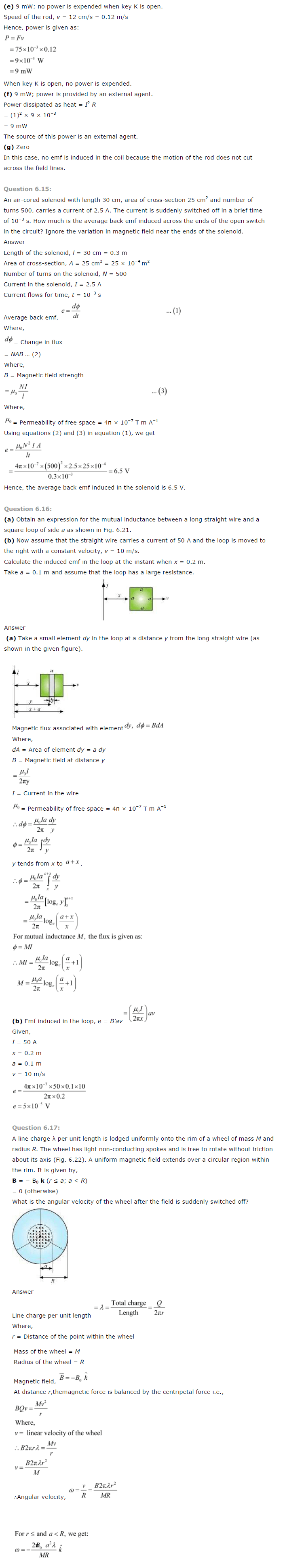
Predict the direction of induced current in the situations described by the following Figs. 6.18(a) to (f).

Show Answer :
Answer :
- According to Lenz’s law, the end of the coil facing S-pole of the magnet will behave as the south pole of the magnet.
- The current induced in the coil will flow clockwise when magnet side is considered. The current flows from (qrpq).
- When the magnet moves in the direction according to Lenz’s law, South pole is developed at end q as well as at end X.
- Therefore, the induced current in the two coils (coil pq and coil XY) should flow clockwise when magnetic side is considered.
- Therefore, the induced current will flow in the direction prqp in coil pq and in the coil XY, induced current will flow in the direction YZXY.
- By Lenz’s law, the induced current in the right loop will be along XYZ.
- By Lenz’s law, the induced current in the left loop will be ZYX.
- By Lenz’s law, the induced current in the right coil will be XrY.
- The current flowing through the straight conductor produces the circular magnetic field which lies in the plane of the loop.
- As no flux is linked with the loop so no current is induced in the loop.
Question : 2
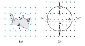
Use Lenz’s law to determine the direction of induced current in the situations described by Fig. 6.19:
(a) A wire of irregular shape turning into a circular shape;
(b) A circular loop being deformed into a narrow straight wire.

Show Answer :
Answer :
According to Lenz’s law, the direction of the induced Emf is such that it tends to produce a current that opposes the change in the magnetic flux that produced it.
(a) When the shape of the wire changes, the flux piercing through the unit surface area increases. As a result, the induced current produces an opposing flux.
Hence, the induced current flows along adcb.
(b) When the shape of a circular loop is deformed into a narrow straight wire, the flux piercing the surface decreases. Hence, the induced current flows along
e= (4×3.14x50x0.1×10)/ (2×3.14×0.2)
e = (5×10⁻⁵V a’d’c’b’)
Question : 3
A long solenoid with 15 turns per cm has a small loop of area 2.0 cm2 placed inside the solenoid normal to its axis.
If the current carried by the solenoid changes steadily from 2.0 A to 4.0 A in 0.1 s, what is the induced emf in the loop while the current is changing?
Show Answer :
Answer :
Given:
Number of turns on the solenoid = 15 turns/cm = 1500 turns/m
Number of turns per unit length, n = 1500 turns
The solenoid has a small loop of area, A =2.0 cm2 = 2 × 10⁻⁴m2
Current carried by the solenoid changes from 2 A to 4 A.
Therefore change in current in the solenoid, di = 4 – 2 = 2 A
Change in time, dt = 0.1 s
Induced emf in the solenoid is given by Faraday’s law as:
e= (dΦ/dt) … (i)
Where, Φ= Induced flux through the small loop
= BA … (ii) Where B = Magnetic field
= (μ0ni) … (iii)
μ0 = Permeability of free space
= (4nx10-7) H/m
Hence, equation (i) reduces to:
e= (d/dt) (di/dt)
= (A μ0 n) x (di/dt)
= (2×10-4x4x3.14×10-7x 1500) x (2/0.1)
=7.54 x 10⁻⁶ V
Hence, the induced voltage in the loop is 7.54×10⁻⁶V
Question : 4
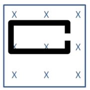
A rectangular wire loop of sides 8 cm and 2 cm with a small cut is moving out of a region of uniform magnetic field of magnitude 0.3 T directed normal to the loop.
What is the emf developed across the cut if the velocity of the loop is
1 cm s–1 in a direction normal to the
(a) longer side,
(b) shorter side of the loop? For how long does the induced voltage last in each case?

Show Answer :
Answer :
Given:
Length of the rectangular wire, l = 8 cm = 0.08 m
Width of the rectangular wire, b = 2 cm = 0.02 m
Hence, area of the rectangular loop, A = lb
= (0.08 × 0.02)
= 16 × 10 – 4
Magnetic field strength, B = 0.3 T
Velocity of the loop, v = 1 cm/s = 0.01 m/s
(a) Emf developed in the loop is given as: e = Blv
= (0.3×0.08×0.01)
=2.4 x10⁻⁴ V
Time taken to travel along the width = (Distance travelled)/ (velocity)
= (b/v)
= (0.02/0.01) =2s
Hence, the induced voltage is 2.4 x10⁻⁴V which lasts for 2 s.
(b) Emf developed, e = Bbv
= 0.3×0.02×0.01
=0.6×10⁻⁴ V
Time taken to travel along the length, t= (Distance travelled)/ (velocity)
= (1/v)
= (0.08)/ (0.01) =8s.
Hence, the induced voltage is (0.6 x10⁻⁴) V which lasts for 8 s.
Mddle block 1
NCERT Solutions Class 12 Physics Electromagnetic Induction
Question : 5
A 1.0 m long metallic rod is rotated with an angular frequency of 400 rad s–1 about an axis normal to the rod passing through its one end.
The other end of the rod is in contact with a circular metallic ring. A constant and uniform magnetic field of 0.5 T parallel to the axis exists everywhere.
Calculate the emf developed between the centre and the ring.
Show Answer :
Answer :
Given:
Length of the rod l = 1m
Angular Frequency of rod ω = 400 rad/s
Magnetic field strength, B = 0.5 T
Linear velocity of fixed end = 0
Linear velocity of other end = l ω (as V = r ω)
Average linear velocity V = (0 + l ω)/ (2)
⇒ V = (l ω)/ (2)
Therefore, Emf developed between the centre and the ring, e = Blv
= (Bl2 ω)/ (2)
= (0.5 x (1)2x 400)/ (2)
=100 V
Hence, the emf developed between the centre and the ring is 100 V.
Question : 6
A circular coil of radius 8.0 cm and 20 turns is rotated about its vertical diameter with an angular speed of 50 rad s–1 in a
uniform horizontal magnetic field of magnitude 3.0 × 10⁻² T. Obtain the maximum and average emf induced in the coil.
If the coil forms a closed loop of resistance 10 Ω, calculate the maximum value of current in the coil.
Calculate the average power loss due to Joule heating. Where does this power come from?
Show Answer :
Answer :
Given:
Max induced emf = 0.603 V
Average induced emf = 0 V
Max current in the coil = 0.0603 A
Average power loss = 0.018 W
Radius of the circular coil, r = 8 cm = 0.08 m
Area of the coil, A = πr
= π × (0.08)2 m2
Number of turns on the coil, N = 20
Angular speed, ω = 50 rad/s
Magnetic field strength, B = 3 × 10⁻² T
Resistance of the loop, R = 10 Ω
Maximum induced emf is given as:
e = (N ω AB)
= (20 × 50 × π × (0.08)2 × 3 × 10−2)
= 0.603 V
The maximum emf induced in the coil is 0.603 V.
Over a full cycle, the average emf induced in the coil is zero.
Maximum current is given as:
I = (e/R)
= (0.603)/ (10)
=0.0603 A
Average power loss due to joule heating:
P = (eI)/ (2)
= ((0.603) x (0.0603))/ (2)
=0.018W
The source of power dissipated as heat in the coil is the external rotor. The current induced in the coil causes a torque which opposes the rotation of the coil,
so the external agent rotor counters this torque to keep the coil rotating uniformly.
Question : 7
A horizontal straight wire 10 m long extending from east to west is falling with a speed of 5.0 m s–1, at right angles
to the horizontal component of the earth’s magnetic field, 0.30 × 10⁻⁴ Wb m–2.
(a) What is the instantaneous value of the emf induced in the wire?
(b) What is the direction of the emf?
(c) Which end of the wire is at the higher electrical potential?
Show Answer :
Answer :
Given:
Length of the wire, l = 10 m
Falling speed of the wire, v = 5.0 m/s
Magnetic field strength, B = 0.3 × 10⁻⁴ Wb m−2
- Using, e =Blv
Therefore, e = (0.3 x 10-4 x 5 x 10)
= 1.5 x 10⁻³ V
- From Fleming’s right hand rule, the direction of induced emf is from west to east.
- As the rod act as a source, the eastern end will have higher electrical potential.
NCERT Solutions Class 12 Physics Electromagnetic Induction
Question : 8
Current in a circuit falls from 5.0 A to 0.0 A in 0.1 s. If an average emf of 200 V induced, give an estimate of the self-inductance of the circuit.
Show Answer :
Answer :
Given:
Initial current, II = 5.0 A
Final current, IF = 0.0 A
Change in current, dI = (IF – II) = 5A
Time taken for the change, t = 0.1 s
Average emf, e = 200 V
For self-inductance (L) of the coil, using relation for average emf as:
e = L (di)/ (dt)
L = (e)/ (di/dt)
= (200)/ (5/0.1)
= 4H
Hence, the self-induction of the coil is 4 H.
Question : 9
A pair of adjacent coils has a mutual inductance of 1.5 H. If the current in one coil changes from 0 to 20 A in 0.5 s,
what is the change of flux linkage with the other coil?
Show Answer :
Answer :
Given:
Mutual inductance of a pair of coils, μ = 1.5 H
Initial current, I1 = 0 A
Final current I2 = 20 A
Change in current, dI = (I2 – I1) = (20 -0) = 20A
Time taken for the change, t = 0.5 s
Induced emf,
e = (dᴓ)/ (dt) (1) where dᴓ = change in the flux linkage in the coil.
Emf is related with mutual inductance as:
e= µ (dI)/ (dt) (2)
Equating equations (1) and (2), we get
(dᴓ)/ (dt) = (µ (dI))/ (dt)
0r dᴓ = (1.5 x 20)
=30Wb
Hence, the change in the flux linkage is 30 Wb.
Question : 10
A jet plane is travelling towards west at a speed of 1800 km/h. What is the voltage difference developed between the ends of the wing having a span of 25 m,
if the Earth’s magnetic field at the location has a magnitude of 5 × 10⁻⁴ T and the dip angle is 30°.
Show Answer :
Answer :
Given:
Speed of the jet plane, v = 1800 km/h = 500 m/s
Wing span of jet plane, l = 25 m
Earth’s magnetic field strength, B = 5.0 × 10⁻⁴ T
Angle of dip, δ = 300
Vertical component of Earth’s magnetic field,
BV = (B sin δ (300))
= (5 × 10⁻⁴ sin 30°)
= (2.5 × 10⁻⁴) T
Voltage difference between the ends of the wing can be calculated as:
e = ((BV) × l × v)
= (2.5 × 10−4 × 25 × 500)
= 3.125 V
Hence, the voltage difference developed between the ends of the wings is
3.125 V.
both move towards the positively charged plate and repel away from the negatively charged plate.
Hence, these two particles are negatively charged. It can also be observed that particle 3 moves
towards the negatively charged plate and repels away from the positively charged plate.
Hence, particle 3 is positively charged.
The charge to mass ratio (emf) is directly proportional to the displacement or amount of deflection for a given velocity.
Since the deflection of particle 3 is the maximum, it has the highest charge to mass ratio.
NCERT Solutions Class 12 Physics Electromagnetic Induction

NCERT Solutions Class 12 Physics Electromagnetic Induction

Bottom Block 3
Multiple Choice Questions Class 12 Physics
Click here to visit Official CBSE website
Click here for NCERT solutions
Click here to visit Official Website of NCERT
Click here to download NCERT Textbooks


